Binary Distillation of Non-Ideal Mixtures Using Driving-Force Diagrams

Initializing live version
Download to Desktop

Requires a Wolfram Notebook System

Interact on desktop, mobile and cloud with the free Wolfram Player or other Wolfram Language products.

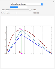
The driving-force diagram for a binary mixture is obtained by plotting versus , where and are the liquid and vapor mole fractions of the light component. Indeed, the driving force is , where and are the vapor-liquid equilibrium (VLE) constants. For example, VLE behavior of a binary mixture composed of pentane and dichloromethane is predicted by setting and .

[more]

The binary mixtures considered here present a positive azeotrope with a composition given by . For this case, the driving-force diagram is composed of two concave curves that intersect at the azeotrope position.

Let us take a saturated liquid feed with a composition, .

If the reflux ratio is equal to , then the operating lines, shown in light blue, intersect at . For , the operating lines are depicted in blue. The slope of the operating lines in the driving-force diagram can be easily related to the reboil and reflux ratios.

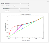
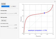
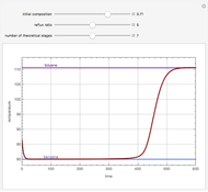
This Demonstration plots the driving-force diagram and the operating lines for and . You can change the value of the VLE behavior of the mixture by changing the values of the VLE constants and . The McCabe–Thiele diagram is also given for both when and . Finally, the minimum reflux ratio is computed in the program by two methods: (1) using the intersection of the feed line and the equilibrium curve (this is the classical McCabe–Thiele method) and (2) using the slope of the light blue operating lines in the driving-force diagram. Both methods give the same result for the minimum reflux ratio. In the present Demonstration, it is assumed that distillate and bottom specifications are mole and mole %, respectively.

One of the snapshot shows interesting behavior: the number of equilibrium stages is very large (exactly 23 plates are needed). This is due to the presence of a tangent pinch. In such a case, the reflux ratio should be increased to avoid having an excessive number of stages. Caution should be exerted when using this method of determination of the minimum reflux ratio because of the possibility of the presence of a tangent pinch.

Here only the left part of the driving-force diagram has been used. It is straightforward to use the right part of this diagram by selecting a feed with a composition above . The distillate would be an almost pure light component and the bottom specification would be a little above the azeotrope's composition.

[less]

Contributed by: Housam Binous (March 2011)
(Kind Fahd University Petroleum & Minerals)
Open content licensed under CC BY-NC-SA


Snapshots


Details

References

[1] R. Gani and E. Bek–Pedersen, "Simple New Algorithm for Distillation Column Design," AIChE Journal, 46(6), 2000 pp. 1271–1274.

[2] E. Bek–Pedersen, R. Gani, and O. Levaux, "Determination of Optimal Energy Efficient Separation Schemes Based on Driving Forces," Computers and Chemical Engineering, 24(2-7), 2000 pp. 253–259.

[3] E. Bek–Pedersen and R. Gani, "Design and Synthesis of Distillation Systems Using a Driving-Force-Based Approach," Chemical Engineering and Processing, 43(3), 2004 pp. 251–262.

[4] W. L. McCabe and E. W. Thiele, "Graphical Design of Fractionating Columns," Industrial and Engineering Chemistry, 17(6), 1925 pp. 605–611.


Feedback (field required)
Email (field required) Name
Occupation Organization
Note: Your message & contact information may be shared with the author of any specific Demonstration for which you give feedback.
Send