Chatter Stability with Orthogonal Rotation


Requires a Wolfram Notebook System
Interact on desktop, mobile and cloud with the free Wolfram Player or other Wolfram Language products.
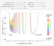
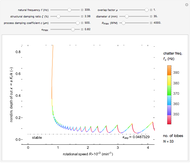
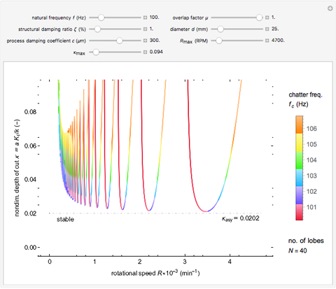
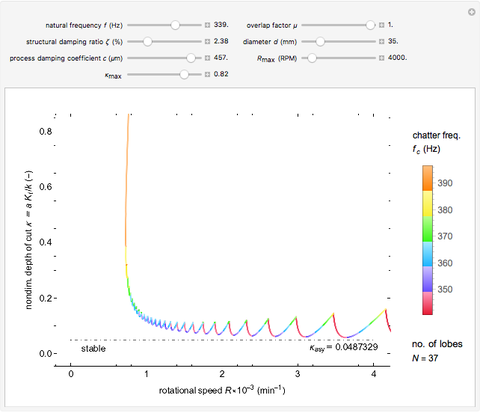
The classical model of regenerative chatter is a simple harmonic oscillator excited by a vibration-dependent force with constant delay. This results in a delay-differential equation whose stability analysis gives rise to a chart demarcating the nondimensionalized depth-of-cut  and the rotational speed
  . The well-developed theory available in [1, 2] is adapted for a general overlap factor
  and process damping
  . This Demonstration studies the effect of natural frequency
  and structural damping ratio
  on the - space and chatter frequency
  at the threshold of stability. Process damping is important at low rotational speeds and high lobe numbers, where the lobed borderline of stability is completely separated from the asymptotic borderline.
Contributed by: Raja Kountanya (May 2014)
Open content licensed under CC BY-NC-SA
Snapshots


Details
Chatter vibration in machining processes is an extremely complex phenomenon; field troubleshooting relies on rigorous data collection and diagnosis by specialists. It also entails expensive downtime and high scrap costs. Chatter is a well-known case of self-excited regenerative vibration, where energy is extracted from the machining process itself. This Demonstration provides a basic insight into the simplest case, that of orthogonal turning. Here, a useful output of the theoretical analysis is the stability chart that demarcates the space of depth of cut and rotational speed into stable and unstable regimes. The stability chart is constructed through a sequence of lobes, each of which prescribes an unstable region.
How the tool and the workpiece interact is modeled as a single-degree-of-freedom system with given resonance frequency  and damping ratio . The cutting stiffness is the force per unit of uncut chip thickness. The nondimensionalized depth of cut is defined as the ratio of the cutting stiffness to the machine stiffness. With
  as the depth of cut,
  as the specific energy, and
  as the structural stiffness, is given by
  . In the literature, is sometimes referred to as the stiffness ratio.
Process damping [1, 2] refers to energy dissipation by the rubbing of the tool flank on the wavy workpiece surface. It is significant at low rotational speeds with a high lobe number. If ignored, the deduced stability chart conflicts with the shop practice of reducing rotational speed to eliminate chatter. That is, if the process is unstable at a higher rotational speed, without process damping, it is necessarily unstable at a lower speed. Another important consideration is the overlap factor, usually assumed to be unity in the literature, that captures the influence of vibration position in the previous rotation.
The workpiece, rotating at a constant rate of rotations per minute, takes the time duration  to complete one rotation. Therefore,
  . The vibration of the tool as a function of time is denoted by
  . With
  as the diameter of the workpiece, the cutting speed of the operation is
  ;
;  is the overlap factor. Process damping is incorporated through the coefficient
  . With reference to Eq. 4.22 in [1],
  . Though has the units of length, its relation to the flank wear land length
  is reported in [1] to be
  . The governing differential equation with this nomenclature is then given by
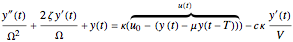 .
.
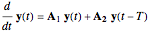
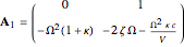
With this formulation, the - space has to be demarcated into stable or unstable regimes. The quantity  can be suitably absorbed into and therefore ignored in the subsequent stability analysis. The state-space method in [3] is a robust way to compute the stability lobes since it employs a free variable
  with fixed bounds.
 ,
,
 ,
,
 ,
,
 ,
,
 ,
,
 ,
,
 .
.
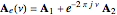
Here, the free variable ,  , is related to the fractional vibrational cycle in one complete rotation of the workpiece and
  represents the angular chatter frequency. The real and imaginary parts of
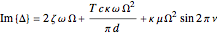
  are zero at the threshold of stability (TOS). These are given by
 ,
,
 .
.
These equations have to be solved simultaneously with  , where
  . Each value of
  gives rise to a stability lobe. The union of all the unstable zones for each gives the complete unstable region in - space, the complement of which is the stable region. At TOS,
  is given by
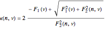 ,
,
where
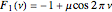 ,
,
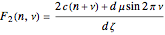 .
.
The chatter frequency  and workpiece rotational speed
  at TOS are given by
 ,
,
 ,
,
where

and  represents the total number of lobes.
  when
when  , but when , is finite and given by greatest integer less than
  , obtained by simultaneous solution of
  and
and  . Also, is given by
 .
.
The intersections of the lobes can be solved to give the lobed borderline of stability (LBS). The lobes are first restricted to bounds  determined from
  . Then, using root-finding, the bounds
  corresponding to the intersection of the
  and
and  lobes are found by simultaneous solution of the equations
 ,
,
 .
.
The asymptotic borderline of stability (ABS), governed purely by structural damping, is given by  . The stable region is indicated by the presence of the word "stable". The number of lobes for given is also displayed.
By varying , , , and , you can study the effect of all the variables. The  and
and  sliders allow rapid zooming in and out to study the stable/unstable regions more closely. The charts have been corroborated with data on p. 139 in [1] and bookmarked in the Demonstration. The chatter frequency at the threshold of stability is shown as a varying color on the LBS. At low , the LBS curve can be seen to move away from the ABS curve completely due to process damping. Its influence on chatter frequency can also be seen clearly.
References
[1] Y. Altintas, Manufacturing Automation: Metal Cutting Mechanics, Machine Tool Vibrations, and CNC Design, Cambridge: Cambridge University Press, 2012.
[2] Y. Altintas, M. Eynian, and H. Onozuka, "Identification of Dynamic Cutting Force Coefficients and Chatter Stability with Process Damping," CIRP Annals, 57, 2008 pp. 371–374. dx.doi.org/10.1016/j.cirp.2008.03.048.
[3] S-G. Chen, A. G. Ulsoy, and Y. Koren, "Computational Stability Analysis of Chatter in Turning," Journal of Manufacturing Science and Engineering, 119(4), 1997 pp. 457–460. dx.doi.org/10.1115/1.2831174.
Permanent Citation
 Asymptotic Stability of Dynamical System by Lyapunov's Direct Method
Housam Binous and Ahmed Bellagi Solution and Stability of a 1-Periodic Differential Equation
Brian G. Higgins and Housam Binous Analog-to-Discrete System Conversion Using Impulse Invariance
Nasser M. Abbasi Study of the Dynamic Behavior of the Lorenz System
Housam Binous and Zakia Nasri Numerical Integration of the Logistic Equation Using Runge-Kutta Methods
Luis Rández Sprott's Jerk Equations
Enrique Zeleny Hopf Bifurcations in a Nonlinear Two-Dimensional Autonomous System
Housam Binous, Ahmed Bellagi, and Brian G. Higgins Colpitts Oscillator
Enrique Zeleny Chaos Induced by Delay in Model of the Immune Response
Clay Gruesbeck A Third-Order Differential Equation with Chaotic Solutions
Clay Gruesbeck
-
 Yield under a Rigid Toroidal Indenter
Raja Kountanya -
 Shear-Angle Models for Oblique Metal Cutting
Raja Kountanya -
 Ray Tracing for Points in a Polygon
Raja Kountanya -
 Boundary and Hole Detection
Raja Kountanya -
 Component Identification and Boundary Delineation
Raja Kountanya -
 Using Eigenvalue Analysis to Rotate in 3D
Raja Kountanya -
 Chatter Stability with Orthogonal Rotation
Raja Kountanya -
 Boundary Value Problems for Cone Geodesics
Raja Kountanya