Fields and Poynting Vector around a Transformer


Requires a Wolfram Notebook System
Interact on desktop, mobile and cloud with the free Wolfram Player or other Wolfram Language products.
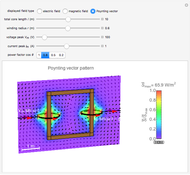
This Demonstration shows the electric and magnetic fields and the Poynting vector distribution associated with a simplified transformer. The sinusoidal frequency of the voltage and the current are assumed to be sufficiently low so that the electric and magnetic fields can be analyzed, assuming static conditions. There is just a single turn for both the primary and secondary windings. However, you can vary the core length and winding radius, as well as the voltage, current, and power factor.
Contributed by: Y. Shibuya (October 2012)
Open content licensed under CC BY-NC-SA
Snapshots


Details
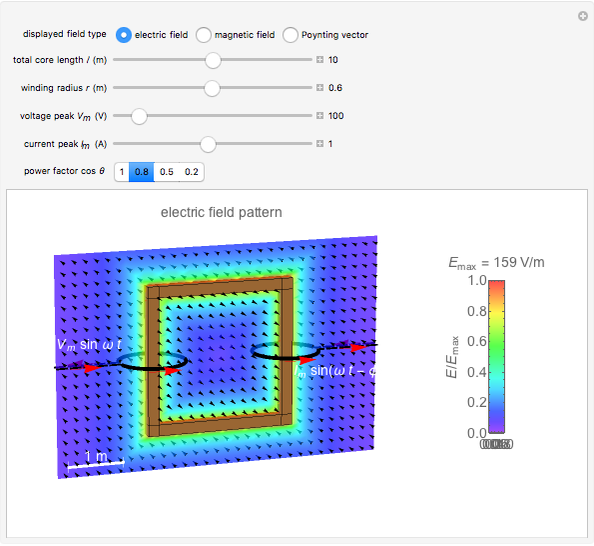
Snapshot 1: electric field
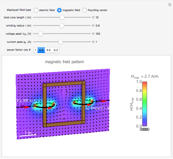
Snapshot 2: magnetic field
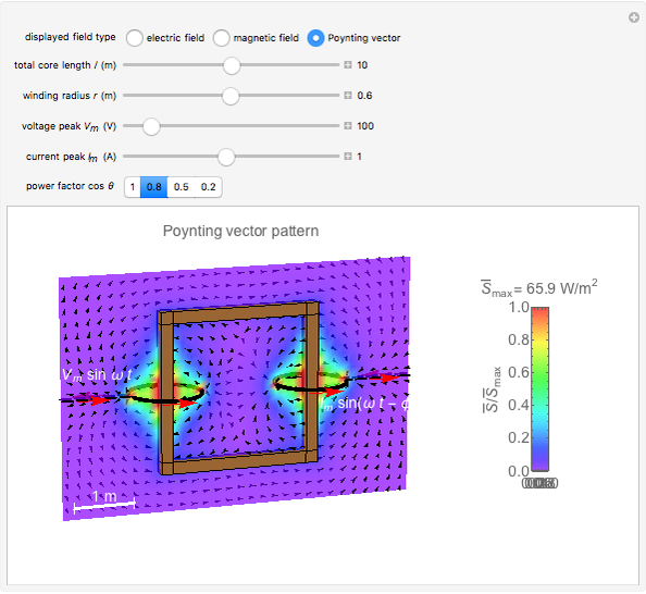
Snapshot 3: Poynting vector
In the simplified one-turn-to-one-turn transformer, the core is assumed to be a square, while the windings are circular filaments. The core's magnetizing current and ohmic loss in the windings are neglected (i.e. the magnetic resistance of the core and the resistance of the wire are assumed to be zero). A core width of 0.2 m and a sectional diameter  0.15 m for the wire are for visual purposes only.
The electric field  is calculated assuming only the induction of main flux. Its peak is given by
  , where
  is the terminal voltage and
  is the distance to the core. The magnetic field
  is calculated by superposing the fields of two ring wires of radius
  carrying a current
  (the formulas involve Bessel functions). Our observations are focused on the plane of the core. The average Poynting vector is calculated using
  , with its direction remaining within the observation plane.
The electric field increases in the vicinity of the core, while the magnetic field increases at the cross sections of the wire. They are mutually perpendicular. The direction of the Poynting vector is predominantly from the primary coil (at the left) toward the secondary (at the right).
As for the route of energy transfer from primary to secondary circuit, it appears that substantial power is carried along the core. The details depend on the transformer configuration and the observation plane.
Reference
[1] J. D. Jackson, Classical Electrodynamics, 3rd ed., New York: John Wiley & Sons, 1998.
Permanent Citation
 Magnetic Field and Magnetic Induction in a Cylindrical Bar Magnet
Y. Shibuya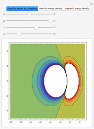 Electromagnetic Energy Density and Poynting Vector of a Relativistic Oscillator
Franz Krafft Motion of a Particle in Crossed Electric and Magnetic Fields
Ji?í Blecha Charged Particle in Uniform Electric and Magnetic Fields
Jeff Bryant and Oleksandr Pavlyk Relativistic Particles in Electric and Magnetic Fields
Ivan Starostin Generating a Rotating Field by Superposition of Three Alternating Fields
Frank Brechtefeld Observing Magnetic Fields with Iron Filings
Enrique Zeleny Cycloidal Path of a Charged Particle in Uniform Perpendicular Electric and Magnetic Fields
Alexander Dalzell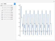 Compass Needle in Uniform and Rotating Magnetic Fields
Enrique Zeleny Rotating Magnetic Field
Rajendra Adhikari
-
 Skin Effects in Straight Wires
Y. Shibuya -
 Leakage Inductance in a Transformer
Y. Shibuya -
 Electromagnetic Wave Scattering by Conducting Sphere
Y. Shibuya -
 Cylindrical Cavity Resonator
Y. Shibuya -
 Electric Fields for Pairs of Cylinders or Spheres
Y. Shibuya -
 Electromagnetic Fields in Wireless Power Transmission
Y. Shibuya -
 Wireless Power Transmission
Y. Shibuya -
 Surge Propagation in a Transmission Line
Y. Shibuya -
 Electron Probability Distribution for the Hydrogen Atom
Y. Shibuya -
 Magnetic Shielding Effect of a Spherical Shell
Y. Shibuya -
 Electromagnetic Waves from a Linear Antenna
Y. Shibuya -
 Current-Carrying Wire in Uniform Magnetic Field
Y. Shibuya -
 Electromagnetic Wave Incident on a Dielectric Boundary
Y. Shibuya -
Magnetic Field and Magnetic Induction in a Cylindrical Bar Magnet
Y. Shibuya -
 Spheroidal Protrusion in a Uniform Electric Field
Y. Shibuya -
 Electrostatic Fields Using Conformal Mapping
Y. Shibuya -
 Dielectric Sphere in a Uniform Electric Field
Y. Shibuya -
 Electromagnetic Waves in Optical Fibers
Y. Shibuya -
 Electromagnetic Waves in a Cylindrical Waveguide
Y. Shibuya -
 Electromagnetic Waves in a Parallel-Plate Waveguide
Y. Shibuya