Polarization of an Optical Wave through Polarizers and Wave Plates

Requires a Wolfram Notebook System
Interact on desktop, mobile and cloud with the free Wolfram Player or other Wolfram Language products.
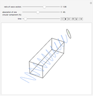
Wave plates and linear polarizers are common optical elements that alter the polarization of light passing through them. This Demonstration shows the effect of the optical element on the polarization of light. You can select the optical element from the drop-down menu and set the polarization state of the incident wave (linear, right circular, or left circular). The line through the optical element represents the direction of polarization (transmission axis) for the polarizer and the fast axis for half- and quarter-wave plates.
Contributed by: Fred E. Moolekamp and Kevin L. Stokes (University of New Orleans) (March 2011)
Open content licensed under CC BY-NC-SA
Snapshots
Details
An electromagnetic (EM) wave propagating in the  direction can be represented mathematically as
 ,
,
where  and
and  are the amplitudes of the
  and
and  components of the electric field,
  is the wave number,
  is the distance along the propagation direction,
  is the frequency,
  is the time, and δ is the phase. The term in brackets is referred to as the Jones vector, which gives the polarization of the wave; for example:
 , linearly polarized light angle
  from the
  axis,
axis,
 , left/right circularly polarized light,
 , elliptically polarized light.
Optical elements that modify polarization are made from anisotropic materials. In an anisotropic material the index of refraction is different for the vertical and horizontal components of the optical wave. For example, quarter-wave plates are typically made from calcite, which is birefringent, and linear polarizers can be made from Polaroid sheets, which are dichroic. Once light passes through these materials, the polarization of the transmitted light changes. Depending on the material and orientation of the incident light, the transmitted light can be linearly or circularly polarized, both of which are special cases of elliptical polarization.
In this Demonstration, we assume the light source was polarized at some point before reaching the origin. Once the light comes into contact with an anisotropic optical element it will go through a change in polarization calculated by using the appropriate Jones matrix. You can choose between three common optical components: a linear polarizer, a quarter-wave plate and a half-wave plate.
Snapshot 1: When a wave comes into contact with a linear polarizer only the components parallel to the transmission angle of the polarizer are transmitted. This also causes it to have a lower amplitude than the incident wave, unless the polarizer and incident wave are polarized in the same direction. The Jones matrix for a linear polarizer with transmission axis oriented at an angle  with the x axis is
 .
.
Snapshot 2: When a quarter-wave plate is used, the  and
and  components of the electric field become 90° or 180° out of phase, respectively. If the incident wave is linearly polarized, the resulting wave is elliptically polarized. Notice that the tip of the electric field vector traces out an ellipse (shown in purple). The Jones matrix for a quarter waveplate is
 .
.
Snapshot 3: Linearly polarized light incident on the quarter-wave plate at 45° results in equal  and
and  components. In this case the transmitted light is circularly polarized, a special case of elliptical polarization.
Snapshot 4: Linearly polarized light incident on a half-wave plate will be rotated.
Suggestion: use a quarter-wave plate and a half-wave plate with circularly polarized incident light and see the results.
Reference:
F. L. Pedrotti and L. S. Pedrotti, Introduction to Optics, 2nd ed., Upper Saddle River, NJ: Prentice Hall, 1993.
Permanent Citation


