Robot Motion with Obstacles


Requires a Wolfram Notebook System
Interact on desktop, mobile and cloud with the free Wolfram Player or other Wolfram Language products.
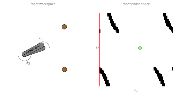
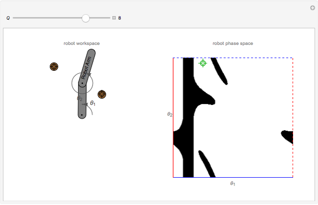
This Demonstration shows a two-link planar arm robot operating in the workspace on the left, containing two small circular obstacles. The corresponding robot phase space on the right shows the configurations  for which an arm intersects an obstacle. You can relocate an obstacle in the workspace and see the corresponding change in phase space. Move the locator in phase space vertically or horizontally to rotate the robot arms. The angles
  and
and  are expressed modulo
  . The obstacle regions are computed using
  unit squares. You can improve the quality of the computation by increasing
  .
.
Contributed by: Aaron T. Becker and Haoran Zhao (April 2016)
Open content licensed under CC BY-NC-SA
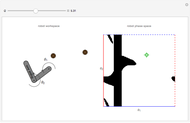
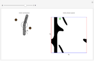
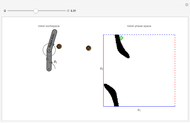
Snapshots


Details
The set of all possible configurations of the robot can be represented in a two-dimensional phase space. Of particular interest are the configurations in which the robot collides with one of the obstacles.
This Demonstration computes the obstacle regions using unit squares and determines if the centroid of each square is in a collision. Given and , the motion computation is trivial.
However, computing the phase-space obstacle region is more difficult, because the size of the space representation grows exponentially with the number of degrees of freedom (independent joints) of the robot.
Consider how many  -dimensional unit squares are required to fill a space of size
  . For a one-dimensional space,
  units are needed. For a two-dimensional space,
  squares are needed. For an -dimensional space,
  hypercubes would be required.
The phase space for a two-link planar robot can be represented on a torus. When rotation joint 1 moves past , it returns to angle 0. This is represented by dashed and solid lines of the same color. If the phase space were printed on a rubber sheet, cut out, and the dashed and solid lines of each color were joined, the resulting shape would be a torus. In this Demonstration, moving the locator past the edge of the phase space wraps the angle around .
Reference
[1] M. Spong, S. Hutchinson, and M. Vidyasagar, Robot Modeling and Control, Hoboken, NJ: John Wiley and Sons, 2006.
Permanent Citation
 Joint Space and Tooling Space for Robot Motion Control
Frederick Wu Fractal Robot Arm
Sándor Kabai Breadth-First Search Robot Motion Planning
Aaron T. Becker, Benedict Isichei and Praveen Reddy Padala Probabilistic Models for Robot Motion
Aaron T. Becker and Renuka Pakeetharan Distance Norms in Robot Workspace and Phase Space
Aaron T. Becker and Benedict Isichei Robot Manipulator Workspaces
Aaron T. Becker, Benedict Isichei, Muhammad Sultan and Maruthi S. Chemudupati Common Robot Arm Configurations
Mohammad Sultan and Aaron T. Becker Manipulability Ellipsoid of a Robot Arm
Aaron T. Becker and Mary Burbage Denavit-Hartenberg Parameters for a Three-Link Robot
Aaron T. Becker and Mary Burbage Distribution of a Robot Swarm in a Square under Gravity
Haoran Zhao and Aaron T. Becker
-
 Distribution of a Swarm of Robots in a Circular Workplace under Gravity
Haoran Zhao -
 Compression Ratio of Spheres in a Curved Tube
Haoran Zhao -
Distribution of a Robot Swarm in a Square under Gravity
Haoran Zhao -
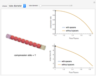 Transmitting Force through a Tube Filled with Spheres and Spacers
Haoran Zhao -
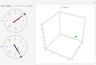 Chart for a Torus
Haoran Zhao -
 Robot Motion with Obstacles
Haoran Zhao