Venn Diagrams for Two-Variable Boolean Logic Circuits


Requires a Wolfram Notebook System
Interact on desktop, mobile and cloud with the free Wolfram Player or other Wolfram Language products.
Venn diagrams are a convenient way to illustrate the relations among disjunctive normal form minterms used in designing logic circuits. This Demonstration presents traditional Venn diagrams for two-variable Boolean logic circuits, with regions corresponding to a value of 1 cross‐hatched. But it does more than that. Alongside each traditional logic circuit Venn diagram, there is a corresponding "mirror image" diagram representing the logic circuit that is a result of reversing the order of the minterms. Viewing traditional and mirrored formats side by side serves as an aid in focusing on the role that minterms play in determining the type of logic circuit that is designed.
[more]


Contributed by: Lawrence J. Thaden (March 2011)
After work by: W. D. Becher
Open content licensed under CC BY-NC-SA
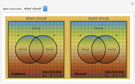
Snapshots
Details
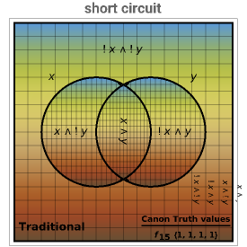
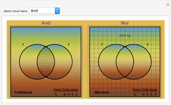
The binary digit expansion of a so-called switching function number is a list of zeros and ones that represents the coefficients of disjunctive normal form (DNF) minterms for the Boolean expression of the function. Whenever a coefficient has the value 1, the region in the Venn diagram representing the minterm appears crosshatched. Examining the pattern of crosshatched regions for a function leads to a deeper appreciation of its unique identity as one of the basic Boolean logic circuits. In this Demonstration the name of the circuit function is indicated at the top of the frame.
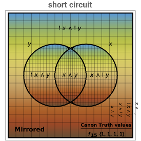
Note that there are two frames for each switching function. The one on the left is labeled "Traditional" while the one on the right is labeled "Mirrored". You can see that the binary digit expansion is the same for both left and right versions, as is shown in the truth values at the bottom-right corner. So how is it that they represent different Boolean logic circuits? If you look carefully at the vertical labels above the truth values, you will see that the "Mirrored" ones are in reverse order compared to the "Traditional" ones, thus leading in most cases to a different set of crosshatched regions in the Venn diagram.
Some might wonder what relevance this has to designing logic circuits. This quote from version 7 of Mathematica explains the relevance.
"Building on its core symbolic architecture, Mathematica gives immediate access to the latest in industrial-strength Boolean computation. With highly general symbolic representations of Boolean functions, with full support for "don't-care" arguments and values, Mathematica provides state-of-the-art Boolean function transformation, minimization, elimination, satisfiability, and analysis, making possible verification, testing and other applications involving hundreds to hundreds of thousands of variables."
Since this mirrored format is the one Wolfram uses, it is my belief that it will gradually replace the traditional format. It is the one to transition to. This Demonstration calls attention to that in an indirect way.
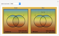
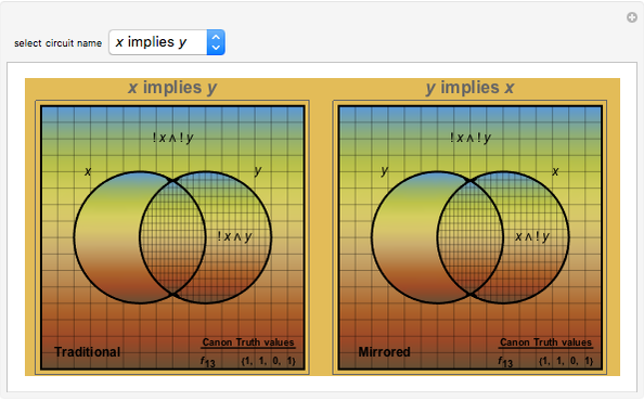
Snapshot 1: truth values remain the same for left and right images while minterms are reversed
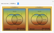
Snapshot 2: reversing the order of the minterms reverses the order of the variables in the implication
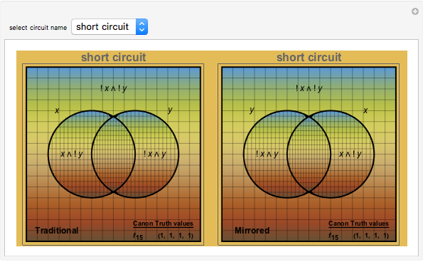
Snapshot 3: short circuit has every region of Venn diagram selected
For more information, see W. D. Becher, Logic Design Using Integrated Circuits, Rochelle Park, NJ: Hayden Book Company, 1977.
Permanent Citation
"Venn Diagrams for Two-Variable Boolean Logic Circuits"
http://demonstrations.wolfram.com/VennDiagramsForTwoVariableBooleanLogicCircuits/
Wolfram Demonstrations Project
Published: March 7 2011
 The Perfect Venn Diagram
Seth J. Chandler Propositional Logic Test
Izidor Hafner Kleene's Three-Valued Logic
Izidor Hafner Venn Diagrams
George Beck and Liz Kent Interactive Venn Diagrams
Marc Brodie (Wheeling Jesuit University)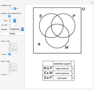 Venn Diagrams and Syllogisms
Izidor Hafner The Chow-Ruskey Order 5 Venn Diagram
Ed Pegg Jr Boolean Primitives as Symmetric Boolean Functions
Roger Germundsson Marquand's Representation of Boolean Functions
Izidor Hafner Sampling of Boolean Functions
Roger Germundsson
