Noise Temperature of a Radar System

Requires a Wolfram Notebook System
Interact on desktop, mobile and cloud with the free Wolfram Player or other Wolfram Language products.
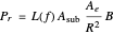
Radar performance is ultimately limited by noise coming from within the radar electronics together with noise that arises from black-body-like radiation from the atmosphere, cosmos, Sun, and ground. By expressing each of these components in terms of an equivalent noise temperature, they can be combined to estimate the effective system noise temperature  at which the radar operates. Once this temperature is known, then the background noise power against which radar detections must be made is simply
  , where
  is Boltzmann's constant and
  is the effective bandwidth of the radar receiver.
Contributed by: Marshall Bradley (April 2014)
Open content licensed under CC BY-NC-SA
Snapshots
Details
The free-space radar range equation relating radar maximum detection range to the key physical parameters describing a radar can be written in the form [1, E. 1.28]
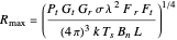 ,
,
where  is the maximum range for which the radar can detect the target,
  is the transmit power of the radar,
  is the transmit antenna gain,
  is the receive antenna gain,
  is the target radar cross section,
  is the wavelength of the radar carrier frequency,
  is the receiver pattern propagation factor,
  is the transmitter pattern propagation factor,
  is Boltzmann's constant
  ),
),  is the system noise temperature in K,
  is the noise bandwidth of the receiver, and
  is the system loss factor. The quantity

in the radar equation is the effective noise spectral density measured in units of power/Hz and referenced to a point just after the receiver antenna output and before the receiver transmission line.
An extremely common mistake in applying the radar equation is to assume that the system noise temperature  is the reference temperature
  , corresponding to the physical temperature of ordinary objects on the surface of the Earth. Actual system noise temperatures can range from 10 K to several thousand degrees K depending on the radar design and operating frequency.
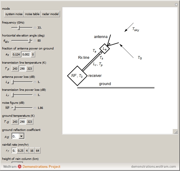
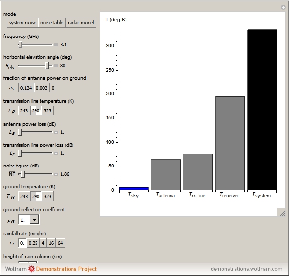
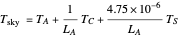
For many radar applications, the radar system noise temperature can be computed using an approach developed in [1] and refined in [2]:
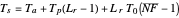 ,
,
where  is the antenna noise temperature,
  is the thermal temperature of the radar transmission line,
  is the power loss in the radar transmission line,
  is the reference temperature 290 °K and
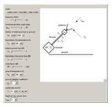
  is the receiver noise figure. The geometry of this situation is shown in snapshot 1. The antenna noise temperature
  contains components from the atmosphere, the Sun, and the cosmos as well as the ground. It can be written in the form
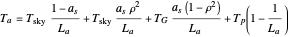 ,
,
where  is the sky noise temperature,
  is the fraction of antenna power that is radiated onto the surface of the ground,
  are the ohmic power losses in the antenna,
  is the amplitude reflection coefficient from the ground,
  is the physical temperature of the ground, and
  is the physical temperature of the antenna. The first term in the preceding equation is the contribution to the antenna noise temperature that comes from the sky via the main lobe of the radar receive beam pattern. The second term represents sky noise that is reflected from the ground. The third term represents radiation from the ground that couples into the system via the receive beam pattern side lobe structure. The fourth term represents noise that is generated within the antenna by virtue of ohmic losses. If there are no ohmic losses in the antenna, then
  and the fourth term is zero. If, on the other hand, there are large ohmic losses, then the fourth term in the limit is
  , the physical temperature of the antenna, and the first three terms are zero.
The received power  from a radar antenna in a lossless medium at wavelength
  due to radiation from a black body at temperature
  located at a distance
  from the radar is
 ,
,
where

is the Planck spectral radiance ( ),
),  is frequency,
  is Planck's constant,
  is the speed of light,
  is the effective area of the radar antenna, and
  is the bandwidth of the radar receiver. If
  denotes the area subtended by the radar receiver beam pattern on the black body and
  is the gain of the radar receive beam, then
  , where
  is the radar receive beam solid angle. Also,
  . Thus it follows that

at radar frequencies. If the radar antenna is polarized, then the received power is simply
 .
.
The sky noise temperature  arises from contributions from the atmosphere, the cosmos, and the Sun. Sky noise temperature
  can be written in the form
 ,
,
where  is the atmospheric (also called tropospheric) noise temperature,
  is the cosmic noise temperature,
  is the brightness temperature of the quiet Sun, and
  are the absorptive propagation losses in the atmosphere. The factor
  in the preceding equation reflects the fact that the Sun is much smaller in angular extent than the sky or atmosphere.
An approximation to the brightness temperature from a quiet Sun based on data presented in [1] and [3] is
 .
.
The cosmic noise temperature can be written in the form
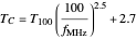 ,
,
where  is the radar frequency in
  and
and  is the cosmic noise temperature at 100 MHz, a quantity that varies between 500 K and 18650 K. The term 2.7 °K in this equation represents isotropic background radiation.
The atmospheric noise temperature  is related to loss-weighted average physical noise temperature
  in the atmosphere and the propagation power loss in the atmosphere via
 .
.
Thus if there are no power losses due to propagation through the atmosphere, then  , and the atmospheric noise temperature is 0. On the other hand, if there are large absorption losses in the atmosphere, the antenna will see the average physical noise temperature
  in the atmosphere. The atmospheric noise temperature is also referred to as the tropospheric noise temperature since only the troposphere is absorptive at frequencies above about 100 MHz. If rain is present, then absorption increases and there is a corresponding increase in the atmospheric noise
  . The key parameters that determine the effects of rain rate on system noise are the rain rate
  in mm/hr and the height of the rain-producing column
  in km.
Snapshot 1: the radar is modeled as a combination of a receiver, a receiver (Rx) transmission line, and an antenna, with each of these three components contributing to system noise in addition to noise contributions from the sky and the ground
References
[1] L. V. Blake, Radar Range-Performance Analysis, Silver Spring, MD: Munro Publishing Co., 1991.
[2] D. K. Barton, Radar Equations for Modern Radar, Boston, MA: Artech House, 2013.
[3] F. I. Shimabukuro and J. M. Stacey, "Brightness Temperature of the Quiet Sun at Centimeter and Millimeter Wavelengths," The Astrophysical Journal, 152, 1968 p. 777.
Permanent Citation
 Atmospheric Radar Wave Absorption
Marshall Bradley MU-MIMO Beamforming by Constructive Interference
Jarek Duda Radio Propagation and Multipath with Diversity Antennas
Allen Hollister Magnetic Resonance Imaging (MRI)
Yuncong Ma Single Signals in Nuclear Magnetic Resonance
Chengchen Guo and Jeffery L. Yarger Multiple Signals in Nuclear Magnetic Resonance
Chengchen Guo and Jeffery L. Yarger NMR Signal Processing Lab: Two Spins-1/2
Russ Bowers Filtering a White-Noise Sequence
David von Seggern Analog-to-Discrete System Conversion Using Impulse Invariance
Nasser M. Abbasi Tempered Fractionally Differenced White Noise
Ian McLeod, Mark Meerschaert and Farzad Sabzikar
-
 Bayesian Distribution of Sample Mean
Marshall Bradley -
 Fluid Flow around a Corner
Marshall Bradley -
 Underwater Vehicle Pressure Signature
Marshall Bradley -
 Extreme Value Forecasting
Marshall Bradley -
 Target Motion with the Metropolis-Hastings Algorithm
Marshall Bradley -
 Noise Temperature of a Radar System
Marshall Bradley -
 High-Frequency Sonar Performance
Marshall Bradley -
Atmospheric Radar Wave Absorption
Marshall Bradley -
 Equine Motion
Marshall Bradley -
 Frequency-Modulated Continuous-Wave (FMCW) Radar
Marshall Bradley -
 Maximum Entropy Probability Density Functions
Marshall Bradley -
 Uncertainty in Sonar Performance Prediction
Marshall Bradley -
 Micro-Doppler Sonar Simulation
Marshall Bradley -
 Human Walking Animation
Marshall Bradley -
 Bayesian Range Weighting for Sonar
Marshall Bradley