Slider and Crank Mechanism

Requires a Wolfram Notebook System
Interact on desktop, mobile and cloud with the free Wolfram Player or other Wolfram Language products.
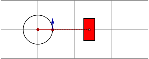
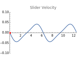
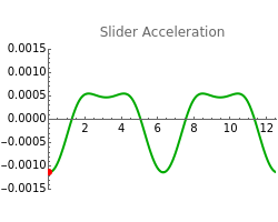
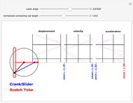
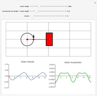
This Demonstration shows the velocity, acceleration, and instantaneous center of rotation for a simple slider-crank mechanism with adjustable crank length and connecting rod to crank length ratio. The connecting rod links the rotating crank to the slider. The velocity vectors for the crank and slider are shown as blue arrows. At any instant, the connecting rod rotates about an instantaneous center of rotation (the intersection of the dashed lines).
Contributed by: Sara McCaslin and Fredericka Brown (May 2010)
Open content licensed under CC BY-NC-SA
Snapshots
Details
The crank is pinned at O, the connecting rod and crank are pinned together at A, and the connecting rod is pinned to the slider at B. Given the angular velocity of the crank, the absolute velocity and acceleration of the crank can be found very quickly.
Because the crank and connecting rod are pinned together at A, we can safely assume that point A on the connecting rod has the same velocity and acceleration as the end of the crank. Likewise, because the slider is pinned to the connecting rod at B, whatever velocity and acceleration values we find for B are valid for the slider, also.
It is important to note that the slider at point B is constrained to move horizontally, so its velocity and acceleration can have only horizontal components. Using relative velocity and acceleration relationships, we can find the velocity and acceleration of the slider:
 ,
,
 ,
,
 ,
,
 ,
,
where  ,
,  ,
,  , and
, and  stand for velocity, angle, radius, and acceleration, respectively.
We are left with four equations,  and
and  both consisting of
  and
and  components, and four unknowns:
  (one unknown, because it is constrained to move in
  ),
),  (one unknown, because it is constrained to move in
  ),
),  , and
, and  .
.
An interesting approach to solving directly for  is based on the concept of instantaneous center of rotation: at any instant in time, the connecting rod AB is essentially rotating about some point in space, called the IC or instantaneous center. This means that we can say AB is in pure rotation about that point. If we can find the distance from the IC to point A, we can determine
  using the simple formula for pure rotation:
  . The instantaneous center for the coupler AB can be found as follows: draw a line perpendicular to the velocity vector at A, draw a line perpendicular to the velocity vector at point B (even though we do not know its magnitude yet, we know it has to be horizontal), and where the two lines intersect we have the IC.
With thanks to Dr. Donald L. Goddard, P.E.
Reference
[1] F. P. Beer, Jr. and E. R. Johnston, Vector Mechanics for Engineers, 7th ed., New York: McGraw-Hill, 2004.
Permanent Citation
