Electromagnetic Waves in a Parallel-Plate Waveguide

Requires a Wolfram Notebook System
Interact on desktop, mobile and cloud with the free Wolfram Player or other Wolfram Language products.
Electromagnetic waves can propagate through a parallel-plate waveguide under appropriate conditions. This Demonstration determines the corresponding fields, energy distributions, and energy transport. The parallel plates support transverse magnetic (TM) and transverse electric (TE) waves. Specifying one of those modes, the mode number  , channel width
  , and frequency
  , the instantaneous fields and energy density distribution are determined for the designated time or phase
  . The maximum electric field is fixed at 1000 V/m in all cases. The frequency has to be higher than the cut-off frequency
  , which is determined by
  and
and  . Taking the wave propagation direction as the
  axis, the fields are function of
  ,
,  , and
, and  . The energy flows along the channel (in the positive
  direction).
Contributed by: Y. Shibuya (December 2012)
Open content licensed under CC BY-NC-SA
Snapshots
Details
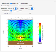
Snapshot 1: the energy density has a maximum at the conductor surface in  mode (TM mode with
  )
)
Snapshot 2: the energy density oscillates three times along the  axis in
  mode
mode
Snapshot 3: the directions of the electrical and magnetic fields mode are interchanged in  mode
mode
Periodic solutions of the wave equation satisfying the boundary conditions  take the following forms, for
  modes:
 ,
,
 ,
,
 ,
,
where  is the angular frequency,
  is the permittivity of air (approximately equal to its vacuum value), and
  is the propagation constant given by
  . The constant
  becomes pure imaginary if the frequency is higher than a certain value, the cut-off frequency. A similar solution is derived for TE modes. The propagation constant and the cut-off frequency are the same.
The energy density can be calculated by  , where
  and
and  are the instantaneous field values. The average Poynting vector is given by
  , which is always in the
  direction.
In the case  ,
,  mode is constructed by
  and
and  with
with  . This means the transverse electromagnetic (TEM). However,
  mode does not exist. If this is selected, no fields are displayed.
It is possible to select the frequency below the cut-off frequency without error. If selected, it will be noted that the energy density is no longer periodic along the  axis, but decays with distance.
The electromagnetic field in parallel plate wave guides can be represented as the superposition of two plane waves reflected at the upper and lower conductor surfaces.
Reference
[1] D. K. Cheng, Field and Wave Electromagnetics, 2nd ed., Reading, MA: Addison-Wesley, 1989.
Permanent Citation


